


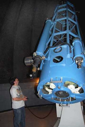
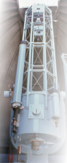
One Tube, Three Mirrors
SRO member Dr. Milan Mijic, Associate Professor of Physics at California State University, Los Angeles (CSULA) is readying the telescope for a night of observing with a group of students and faculty visiting from the Science Visualization Laboratory at CalState LA.
The main mirror, which rests inside the tailpiece shown here, gathers starlight but where that light is focused depends upon an additional reflecting surface (the "secondary") near the top of the tube.
If a flat mirror is installed there, angled at 45 degrees, light is redirected out the side of the tube. This is known as the Newtonian configuration, first perfected by Isaac Newton in 1668.
Alternatively, if the secondary is convex, the light is reflected back toward the primary, escaping the tube through concentric holes in the main mirror and the tailpiece. This optical arrangement is referred to as a "Cassegrain."
The back of the primary mirror is visible through the three cutouts in the tube's rear bulkhead. As the telescope is moved, the heavy glass disk is subject to sagging and thus distortion of the precise curve on its front surface. To prevent this from happening, the mirror must be supported at several strategic points from the back. This is provided by the white pads that can be clearly seen.
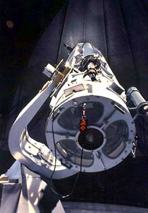
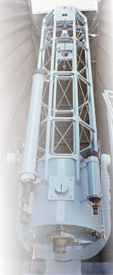
A Compact, Robust Mount for a Massive Telescope
Fork mounts are harder to fabricate than other designs, requiring precision on a scale that isn't easy to achieve. Yet telescopes of a size like the Carroll reflector have few other good options.
Notice the hand holds on the periphery of the tube's tail piece. The telescope is so well accommodated in the fork mount that moving it by hand takes surprisingly little effort, though the motor engagment clutches must be loosened first.
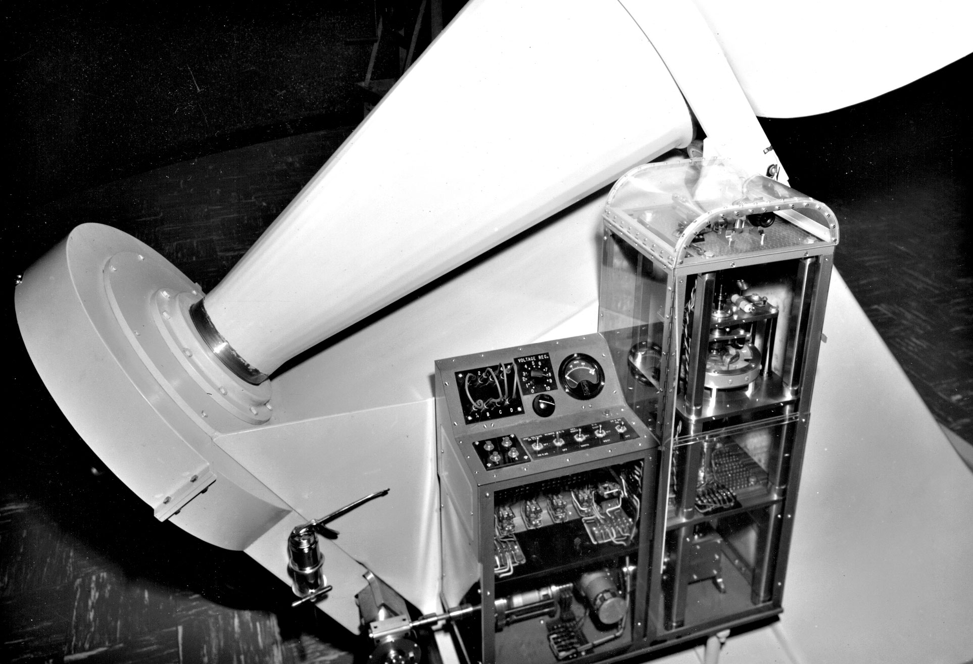
A Novel Approach to Stopping Earth's Rotation
Any research-grade telescope must be able to effectively counteract the effects of Earth's rotation. Typically, this starts by first aligning the polar axis of an equatorial mount to the place in the sky about which the stars appear to "spin." This is a point quite near Polaris, the North Star. Pictured above, the cone of the Carroll telescope's polar axis is so-oriented.
Having done that, the polar axis can then be driven at a rate which follows an object's march across the sky. For most targets, like stars, galaxies, and the planets, this roughly equates to 1 revolution per day. But for the Moon, some asteroids and comets, variable rates of rotation may be necessary. The Carroll telescope has such a range of motor speeds on both axes.
For the 30-inch telescope's RA axis, this was provided by an elaborate and handsomely constructed system based on 28v DC components and a friction drive. In this photo, undoubtedly taken when the telescope was new, they are ready to begin two decades of work of faithfully "freezing" the Earth's eastward rotation as observers locked in on various targets in the skies above Charlton Flats.
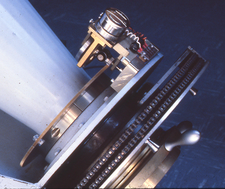
Upgrades
Beginning in the 1980s, significant changes to the mount's subsystems were made. One of the first was to adopt 110v as the source standard, this to replace the 28v system (that had been transformed and rectified from 110) that powered components of the original drive system.
The "new" spur gear set and small driving motor as well as the dual chains from that earlier era are pictured here as they appeared in 1982. Advanced technologies offer the promise of an improved experience but don't always translate for a variety of reasons. This modification did not prove successful and was later removed.
The brass plate with silver handles has a nautical look but isn't used to steer - it is the RA friction clutch. When released, it allows the telescope's polar axis to be rotated manually for gross positioning or maintenance.

"Don't Blink and You'll Miss It...?!"
This machine, called a "Blink Comparator," was used to find new solar system objects, including asteroids. https://creativecommons.org/licenses/by/2.0/
"Don't Blink and You'll Miss It...?!"
This machine, called a "Blink Comparator," was used to find new solar system objects, including asteroids. https://creativecommons.org/licenses/by/2.0/
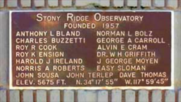
In Memoriam...
The individuals who founded SRO comprised a range of talent and of age. Youthful in spirit and determination, all, for nothing less could have crossed a finish line that sometimes seemed as distant as the stars themselves.
None of the founding members are still alive. The last of them, John Sousa, was a young man when they began their journey of dreams and toil, and the last to set foot inside the dome. Perhaps when nearing the doorway on that final visit he paused to see his name clustered with the others as shown here, and thought back to a day of satisfaction and triumph when they posed for the photo on this page.
They gathered just steps away from where this plaque is permanently installed, each man having taken a leap of faith in the others and landing, shoulder to shoulder, at the mountaintop
temple of their making.
One Tube, Three Mirrors
Dr. Milan Mijic, Associate-member at SRO and Associate Professor of Physics at California State University, Los Angeles (CSULA) is readying the telescope for a night of observing with a group of students and faculty visiting from the Science Visualization Laboratory at CalState LA.
The main mirror, which rests inside the tailpiece shown here, gathers starlight but where that light is focused depends upon a second reflecting surface near the top of the tube.
If a flat mirror is used, angled at 45 degrees to the light path, light is reflected out the side of the tube. This is known as the Newtonian configuration, first perfected by Isaac Newton in 1668.
Alternatively, if a convex mirror is used instead, the light is reflected back toward the primary, escaping the tube through concentric holes in the mirror and the tailpiece. This optical arrangement is referred to as a "Cassegrain."
The back of the primary mirror is seen through the three cutouts in the tube's tailpiece. To prevent sagging and preserve the precise curve on the glass's surface as the telescope moves, the mirror must be supported at several strategic points from the back. This is provided by the white pads that can be clearly seen.
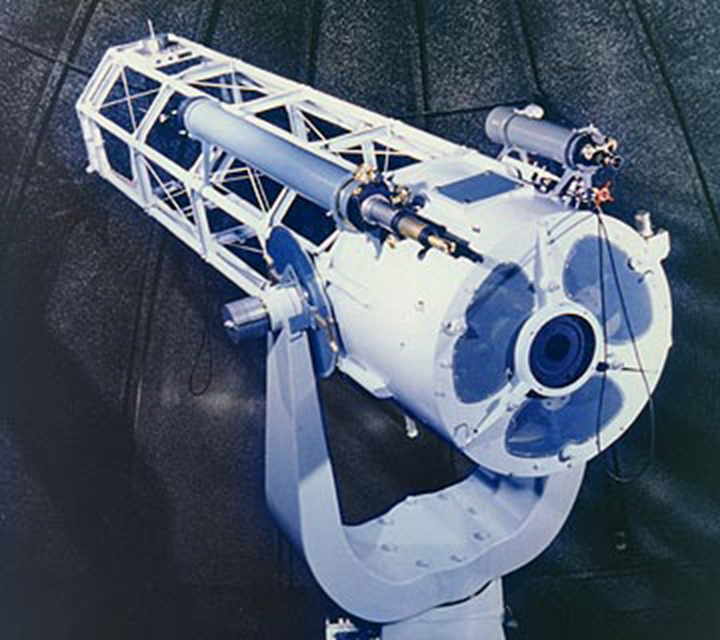
The primary instrument at SRO is a fork-mounted, 30-inch (0.76-m) reflecting telescope having two configurations (ratios): Newtonian (f/6) or Cassegrain (f/25). This superb instrument was designed and built by George A. Carroll with considerable help from the members of Stony Ridge Observatory.
When completed in 1963, Stony Ridge’s 30-inch telescope was the eighth-largest telescope in California, and most likely the largest amateur telescope in the world.
Between 1957 and 1963, SRO members produced a film that documented the progress of the construction of the telescope and observatory – from the delivery of the mirror blank for grinding and polishing in Altadena, CA, to the opening of the dome and celebration of first-light in 1963. You may view or download a digital version here.
One unique design feature of the telescope was the use of a dual-chain, friction drive system that did not rely on expensive, high-precision gears to accurately move the telescope to follow the stars in the sky. This system has worked with accuracy and precision for 47 years.
The primary mirror, made from a disk of Hayward C-3 glass, was ground and polished by members of SRO under the direction of Roy Ensign and Easy Sloman. Roy did the final polishing,figuring and testing of the mirror.
The raw glass blank started out weighing over 400 pounds(181 kg) and was several inches thicker than it is now. The finished mirror tips the scale at about 300 pounds (136 kg) and is 5-inches (12.5 cm) thick (a thickness ratio of 6:1 was typical for astronomical mirrors of that time). Any amateur telescope maker who has “pushed glass” will certainly wince at that amount of glass worn away. But thanks to Roy’s motorized grinding machine, the grinding was only endlessly noisy and nerve racking, not muscle stressing.
Four eyepiece/instrument ports, located near the top end of the telescope tube at the Newtonian focus, are positioned at each of the 4 cardinal points. A rotating secondary mirror is computer controlled (a recent upgrade) to position itself to reflect the image path to the desired observing port.
A fifth port is located at the back of the telescope tube, at the Cassegrain focus.
The Newtonian secondary flat-mirror is switched out with a round convex-mirror that reflects the image from the primary mirror, returning it back to the primary and through a hole in the center of that mirror, to the Cassegrain focus, located outside the back of the tube.
The main telescope tube has two refractor telescopes mounted to it, a 5-inch (12.5 cm) f/5, and a 6-inch (15.2 cm) f/15 telescope. These instruments, including the optical glass lens elements, were both designed and built by George Carroll.
The 6-inch telescope has an movable x/y stage in front of the eyepiece which allows the observer to reposition the image in relation to the image being observed through the 30-inch. This feature is particularly useful when selecting guide stars when imaging through the main telescope.
Upgrades to the telescope
As new technologies have been developed through the years, Stony Ridge Observatory has endeavored to keep pace.
As a longtime SRO member, Timothy Cann has been Stony Ridge’s guiding light through these years of paradigm shifts. A professional IT consultant by trade, with the passion and skills to produce high-precision machine work, Tim has continued to keep the parts of the mechanism called Stony Ridge Observatory repaired, greased, maintained and moving forward for many years.
During the 1980’s, one of Tim’s first upgrades was to convert the telescope’s electrical system, a 28-volt DC system borrowed from George Carroll‘s professional occupation as an aircraft designer, to a “modern-day” 110-volt AC system. This upgrade required a complete rebuild of the original drive motors.
![]()

The photo above (courtesy Elizabeth Erin Crossman, CSULA) shows Dr. Milan Mijic, Associate-member at SRO and Associate Professor of Physics at California State University, Los Angeles (CSULA) readying the telescope for a group of students and faculty visiting from the Science Visualization Laboratory at CalState LA for a night of observing. Click on the image for a high-res, 800KB version.
***************************
Later, the remote servos, devices that connected to clock faces that were used to tell the observer where the telescope was pointed on the sky, were replaced by digital encoders and digital position readout displays.
After that came the addition of a digital computer interface that allowed off-the-shelf telescope control software to read the telescope’s position.
The stage had been set for the latest upgrade. The computer could understand where the telescope was pointing, but the telescope couldn’t understand anything the computer was saying to it, a situation called an open-loop. Closing this loop would require the retirement of the original 2-chain drive system.
A new harmonic-drive system was recently designed and installed by Tim Cann, replacing the original chain drive, and closing the loop. The telescope is now “smart” enough to understand what the computer tells it to do, how fast to move and where to go. The new drive system is operational and currently undergoing engineering tests.
The Station Fire, which nearly destroyed the observatory in the summer of 2009, has delayed the continued use of the telescope, the engineering tests, and the astronomical and outreach projects that were in progress.
scb 5/7/2010
The photo below shows Dave Thomas adjusting the RA clutch. The original drive motor can be seen in the taller of 2 plexiglass cabinets. Relays and gearing are housed in the shorter cabinet.
A Compact, Robust Mount for a Massive Telescope
Fork mounts are harder to fabricate than other designs, requiring precision on a scale that isn't easy to achieve. Yet telescopes of a size like the Carroll reflector have few other good choices.
Notice the hand holds on the tail piece of the tube. The telescope is so well accommodated in the fork mount that moving it by hand takes suprisingly little effort.
As received, the raw glass blank weighed over 400 pounds (181 kg) and much thicker than it is now. The finished mirror tips the scale at about 300 pounds (136 kg) and is 5-inches (12.5 cm) thick, a typical proportion for a 30 inch diameter mirror. (A 6:1 ratio was typical for that era.)
Any amateur telescope maker who has “pushed glass” will certainly wince at that amount of material that had to be worn away. But thanks to Roy’s motorized grinding machine, the removal was only endlessly noisy and nerve racking, not laborious.
Four eyepiece/instrument ports, located near the top end of the telescope tube at the Newtonian focus, are positioned at each of the 4 cardinal points. A rotating secondary mirror is computer controlled (a recent upgrade) to position itself to reflect the image path to the desired observing port.
A fifth port is located at the back of the telescope tube, at the Cassegrain focus.
The Newtonian secondary flat-mirror is switched out with a round convex-mirror that reflects the image from the primary mirror, returning it back to the primary and through a hole in the center of that mirror, to the Cassegrain focus, located outside the back of the tube.
When completed in 1963, Stony Ridge’s 30-inch telescope was the eighth-largest telescope in California, and most likely the largest amateur telescope in the world.
Between 1957 and 1963, SRO members produced a film that documented the progress of the construction of the telescope and observatory – from the delivery of the mirror blank for grinding and polishing in Altadena, CA, to the opening of the dome and celebration of first-light in 1963. You may view or download a digital version here.
One unique design feature of the telescope was the use of a dual-chain, friction drive system that did not rely on expensive, high-precision gears to accurately move the telescope to follow the stars in the sky. This system has worked with accuracy and precision for 47 years.
The primary mirror, made from a disk of Hayward C-3 glass, was ground and polished by members of SRO under the direction of Roy Ensign and Easy Sloman. Roy did the final polishing,figuring and testing of the mirror.
The raw glass blank started out weighing over 400 pounds(181 kg) and was several inches thicker than it is now. The finished mirror tips the scale at about 300 pounds (136 kg) and is 5-inches (12.5 cm) thick (a thickness ratio of 6:1 was typical for astronomical mirrors of that time). Any amateur telescope maker who has “pushed glass” will certainly wince at that amount of glass worn away. But thanks to Roy’s motorized grinding machine, the grinding was only endlessly noisy and nerve racking, not muscle stressing.
Four eyepiece/instrument ports, located near the top end of the telescope tube at the Newtonian focus, are positioned at each of the 4 cardinal points. A rotating secondary mirror is computer controlled (a recent upgrade) to position itself to reflect the image path to the desired observing port.
A fifth port is located at the back of the telescope tube, at the Cassegrain focus.
The Newtonian secondary flat-mirror is switched out with a round convex-mirror that reflects the image from the primary mirror, returning it back to the primary and through a hole in the center of that mirror, to the Cassegrain focus, located outside the back of the tube.
The main telescope tube has two refractor telescopes mounted to it, a 5-inch (12.5 cm) f/5, and a 6-inch (15.2 cm) f/15 telescope. These instruments, including the optical glass lens elements, were both designed and built by George Carroll.
The 6-inch telescope has an movable x/y stage in front of the eyepiece which allows the observer to reposition the image in relation to the image being observed through the 30-inch. This feature is particularly useful when selecting guide stars when imaging through the main telescope.
Upgrades to the telescope
As new technologies have been developed through the years, Stony Ridge Observatory has endeavored to keep pace.
As a longtime SRO member, Timothy Cann has been Stony Ridge’s guiding light through these years of paradigm shifts. A professional IT consultant by trade, with the passion and skills to produce high-precision machine work, Tim has continued to keep the parts of the mechanism called Stony Ridge Observatory repaired, greased, maintained and moving forward for many years.
During the 1980’s, one of Tim’s first upgrades was to convert the telescope’s electrical system, a 28-volt DC system borrowed from George Carroll‘s professional occupation as an aircraft designer, to a “modern-day” 110-volt AC system. This upgrade required a complete rebuild of the original drive motors.
![]()
The photo above (courtesy Elizabeth Erin Crossman, CSULA) shows Dr. Milan Mijic, Associate-member at SRO and Associate Professor of Physics at California State University, Los Angeles (CSULA) readying the telescope for a group of students and faculty visiting from the Science Visualization Laboratory at CalState LA for a night of observing. Click on the image for a high-res, 800KB version.
***************************
Later, the remote servos, devices that connected to clock faces that were used to tell the observer where the telescope was pointed on the sky, were replaced by digital encoders and digital position readout displays.
After that came the addition of a digital computer interface that allowed off-the-shelf telescope control software to read the telescope’s position.
The stage had been set for the latest upgrade. The computer could understand where the telescope was pointing, but the telescope couldn’t understand anything the computer was saying to it, a situation called an open-loop. Closing this loop would require the retirement of the original 2-chain drive system.
A new harmonic-drive system was recently designed and installed by Tim Cann, replacing the original chain drive, and closing the loop. The telescope is now “smart” enough to understand what the computer tells it to do, how fast to move and where to go. The new drive system is operational and currently undergoing engineering tests.
The Station Fire, which nearly destroyed the observatory in the summer of 2009, has delayed the continued use of the telescope, the engineering tests, and the astronomical and outreach projects that were in progress.
scb 5/7/2010
The photo below shows Dave Thomas adjusting the RA clutch. The original drive motor can be seen in the taller of 2 plexiglass cabinets. Relays and gearing are housed in the shorter cabinet.
The primary instrument at SRO is a fork-mounted, 30-inch (0.76-m) reflecting telescope having two configurations (ratios): Newtonian (f/6) or Cassegrain (f/25). This superb instrument was designed and built by George A. Carroll with considerable help from the members of Stony Ridge Observatory.
When completed in 1963, Stony Ridge’s 30-inch telescope was the eighth-largest telescope in California, and most likely the largest amateur telescope in the world.
Between 1957 and 1963, SRO members produced a film that documented the progress of the construction of the telescope and observatory – from the delivery of the mirror blank for grinding and polishing in Altadena, CA, to the opening of the dome and celebration of first-light in 1963. You may view or download a digital version here.
One unique design feature of the telescope was the use of a dual-chain, friction drive system that did not rely on expensive, high-precision gears to accurately move the telescope to follow the stars in the sky. This system has worked with accuracy and precision for 47 years.
The primary mirror, made from a disk of Hayward C-3 glass, was ground and polished by members of SRO under the direction of Roy Ensign and Easy Sloman. Roy did the final polishing,figuring and testing of the mirror.
The raw glass blank started out weighing over 400 pounds(181 kg) and was several inches thicker than it is now. The finished mirror tips the scale at about 300 pounds (136 kg) and is 5-inches (12.5 cm) thick (a thickness ratio of 6:1 was typical for astronomical mirrors of that time). Any amateur telescope maker who has “pushed glass” will certainly wince at that amount of glass worn away. But thanks to Roy’s motorized grinding machine, the grinding was only endlessly noisy and nerve racking, not muscle stressing.
Four eyepiece/instrument ports, located near the top end of the telescope tube at the Newtonian focus, are positioned at each of the 4 cardinal points. A rotating secondary mirror is computer controlled (a recent upgrade) to position itself to reflect the image path to the desired observing port.
A fifth port is located at the back of the telescope tube, at the Cassegrain focus.
The Newtonian secondary flat-mirror is switched out with a round convex-mirror that reflects the image from the primary mirror, returning it back to the primary and through a hole in the center of that mirror, to the Cassegrain focus, located outside the back of the tube.
The main telescope tube has two refractor telescopes mounted to it, a 5-inch (12.5 cm) f/5, and a 6-inch (15.2 cm) f/15 telescope. These instruments, including the optical glass lens elements, were both designed and built by George Carroll.
The 6-inch telescope has an movable x/y stage in front of the eyepiece which allows the observer to reposition the image in relation to the image being observed through the 30-inch. This feature is particularly useful when selecting guide stars when imaging through the main telescope.
Upgrades to the telescope
As new technologies have been developed through the years, Stony Ridge Observatory has endeavored to keep pace.
As a longtime SRO member, Timothy Cann has been Stony Ridge’s guiding light through these years of paradigm shifts. A professional IT consultant by trade, with the passion and skills to produce high-precision machine work, Tim has continued to keep the parts of the mechanism called Stony Ridge Observatory repaired, greased, maintained and moving forward for many years.
During the 1980’s, one of Tim’s first upgrades was to convert the telescope’s electrical system, a 28-volt DC system borrowed from George Carroll‘s professional occupation as an aircraft designer, to a “modern-day” 110-volt AC system. This upgrade required a complete rebuild of the original drive motors.
![]()
The photo above (courtesy Elizabeth Erin Crossman, CSULA) shows Dr. Milan Mijic, Associate-member at SRO and Associate Professor of Physics at California State University, Los Angeles (CSULA) readying the telescope for a group of students and faculty visiting from the Science Visualization Laboratory at CalState LA for a night of observing. Click on the image for a high-res, 800KB version.
***************************
Later, the remote servos, devices that connected to clock faces that were used to tell the observer where the telescope was pointed on the sky, were replaced by digital encoders and digital position readout displays.
After that came the addition of a digital computer interface that allowed off-the-shelf telescope control software to read the telescope’s position.
The stage had been set for the latest upgrade. The computer could understand where the telescope was pointing, but the telescope couldn’t understand anything the computer was saying to it, a situation called an open-loop. Closing this loop would require the retirement of the original 2-chain drive system.
A new harmonic-drive system was recently designed and installed by Tim Cann, replacing the original chain drive, and closing the loop. The telescope is now “smart” enough to understand what the computer tells it to do, how fast to move and where to go. The new drive system is operational and currently undergoing engineering tests.
The Station Fire, which nearly destroyed the observatory in the summer of 2009, has delayed the continued use of the telescope, the engineering tests, and the astronomical and outreach projects that were in progress.
scb 5/7/2010
The photo below shows Dave Thomas adjusting the RA clutch. The original drive motor can be seen in the taller of 2 plexiglass cabinets. Relays and gearing are housed in the shorter cabinet.
A Novel Approach to Stopping Earth's Rotation
Any research-grade telescope must be able to counteract the effects of Earth's rotation. Typically, this is done by first aligning the polar axis of an equatorial mount to the place in the sky about which the stars appear to "spin." This is a point quite near Polaris, the North Star. Pictured above, the cone of the Carroll telescope's polar axis is so-oriented.
Having done that, the polar axis can then be driven at a rate which matches an object's march across the sky. For most objects like stars, galaxies, and the planets, this roughly equates to 1 revolution per day. But for the moon, some asteroids and comets, higher rates of rotation are necessary to keep pace with their motion. The Carroll telescope has such a range of tracking speeds.
As received, the raw glass blank weighed over 400 pounds (181 kg) and much thicker than it is now. The finished mirror tips the scale at about 300 pounds (136 kg) and is 5-inches (12.5 cm) thick, a typical proportion for a 30 inch diameter mirror. (A 6:1 ratio was typical for that era.)
Any amateur telescope maker who has “pushed glass” will certainly wince at that amount of material that had to be worn away. But thanks to Roy’s motorized grinding machine, the removal was only endlessly noisy and nerve racking, not laborious.
Four eyepiece/instrument ports, located near the top end of the telescope tube at the Newtonian focus, are positioned at each of the 4 cardinal points. A rotating secondary mirror is computer controlled (a recent upgrade) to position itself to reflect the image path to the desired observing port.
A fifth port is located at the back of the telescope tube, at the Cassegrain focus.
The Newtonian secondary flat-mirror is switched out with a round convex-mirror that reflects the image from the primary mirror, returning it back to the primary and through a hole in the center of that mirror, to the Cassegrain focus, located outside the back of the tube.
When completed in 1963, Stony Ridge’s 30-inch telescope was the eighth-largest telescope in California, and most likely the largest amateur telescope in the world.
Between 1957 and 1963, SRO members produced a film that documented the progress of the construction of the telescope and observatory – from the delivery of the mirror blank for grinding and polishing in Altadena, CA, to the opening of the dome and celebration of first-light in 1963. You may view or download a digital version here.
One unique design feature of the telescope was the use of a dual-chain, friction drive system that did not rely on expensive, high-precision gears to accurately move the telescope to follow the stars in the sky. This system has worked with accuracy and precision for 47 years.
The primary mirror, made from a disk of Hayward C-3 glass, was ground and polished by members of SRO under the direction of Roy Ensign and Easy Sloman. Roy did the final polishing,figuring and testing of the mirror.
The raw glass blank started out weighing over 400 pounds(181 kg) and was several inches thicker than it is now. The finished mirror tips the scale at about 300 pounds (136 kg) and is 5-inches (12.5 cm) thick (a thickness ratio of 6:1 was typical for astronomical mirrors of that time). Any amateur telescope maker who has “pushed glass” will certainly wince at that amount of glass worn away. But thanks to Roy’s motorized grinding machine, the grinding was only endlessly noisy and nerve racking, not muscle stressing.
Four eyepiece/instrument ports, located near the top end of the telescope tube at the Newtonian focus, are positioned at each of the 4 cardinal points. A rotating secondary mirror is computer controlled (a recent upgrade) to position itself to reflect the image path to the desired observing port.
A fifth port is located at the back of the telescope tube, at the Cassegrain focus.
The Newtonian secondary flat-mirror is switched out with a round convex-mirror that reflects the image from the primary mirror, returning it back to the primary and through a hole in the center of that mirror, to the Cassegrain focus, located outside the back of the tube.
The main telescope tube has two refractor telescopes mounted to it, a 5-inch (12.5 cm) f/5, and a 6-inch (15.2 cm) f/15 telescope. These instruments, including the optical glass lens elements, were both designed and built by George Carroll.
The 6-inch telescope has an movable x/y stage in front of the eyepiece which allows the observer to reposition the image in relation to the image being observed through the 30-inch. This feature is particularly useful when selecting guide stars when imaging through the main telescope.
Upgrades to the telescope
As new technologies have been developed through the years, Stony Ridge Observatory has endeavored to keep pace.
As a longtime SRO member, Timothy Cann has been Stony Ridge’s guiding light through these years of paradigm shifts. A professional IT consultant by trade, with the passion and skills to produce high-precision machine work, Tim has continued to keep the parts of the mechanism called Stony Ridge Observatory repaired, greased, maintained and moving forward for many years.
During the 1980’s, one of Tim’s first upgrades was to convert the telescope’s electrical system, a 28-volt DC system borrowed from George Carroll‘s professional occupation as an aircraft designer, to a “modern-day” 110-volt AC system. This upgrade required a complete rebuild of the original drive motors.
![]()
The photo above (courtesy Elizabeth Erin Crossman, CSULA) shows Dr. Milan Mijic, Associate-member at SRO and Associate Professor of Physics at California State University, Los Angeles (CSULA) readying the telescope for a group of students and faculty visiting from the Science Visualization Laboratory at CalState LA for a night of observing. Click on the image for a high-res, 800KB version.
***************************
Later, the remote servos, devices that connected to clock faces that were used to tell the observer where the telescope was pointed on the sky, were replaced by digital encoders and digital position readout displays.
After that came the addition of a digital computer interface that allowed off-the-shelf telescope control software to read the telescope’s position.
The stage had been set for the latest upgrade. The computer could understand where the telescope was pointing, but the telescope couldn’t understand anything the computer was saying to it, a situation called an open-loop. Closing this loop would require the retirement of the original 2-chain drive system.
A new harmonic-drive system was recently designed and installed by Tim Cann, replacing the original chain drive, and closing the loop. The telescope is now “smart” enough to understand what the computer tells it to do, how fast to move and where to go. The new drive system is operational and currently undergoing engineering tests.
The Station Fire, which nearly destroyed the observatory in the summer of 2009, has delayed the continued use of the telescope, the engineering tests, and the astronomical and outreach projects that were in progress.
scb 5/7/2010
The photo below shows Dave Thomas adjusting the RA clutch. The original drive motor can be seen in the taller of 2 plexiglass cabinets. Relays and gearing are housed in the shorter cabinet.
The primary instrument at SRO is a fork-mounted, 30-inch (0.76-m) reflecting telescope having two configurations (ratios): Newtonian (f/6) or Cassegrain (f/25). This superb instrument was designed and built by George A. Carroll with considerable help from the members of Stony Ridge Observatory.
When completed in 1963, Stony Ridge’s 30-inch telescope was the eighth-largest telescope in California, and most likely the largest amateur telescope in the world.
Between 1957 and 1963, SRO members produced a film that documented the progress of the construction of the telescope and observatory – from the delivery of the mirror blank for grinding and polishing in Altadena, CA, to the opening of the dome and celebration of first-light in 1963. You may view or download a digital version here.
One unique design feature of the telescope was the use of a dual-chain, friction drive system that did not rely on expensive, high-precision gears to accurately move the telescope to follow the stars in the sky. This system has worked with accuracy and precision for 47 years.
The primary mirror, made from a disk of Hayward C-3 glass, was ground and polished by members of SRO under the direction of Roy Ensign and Easy Sloman. Roy did the final polishing,figuring and testing of the mirror.
The raw glass blank started out weighing over 400 pounds(181 kg) and was several inches thicker than it is now. The finished mirror tips the scale at about 300 pounds (136 kg) and is 5-inches (12.5 cm) thick (a thickness ratio of 6:1 was typical for astronomical mirrors of that time). Any amateur telescope maker who has “pushed glass” will certainly wince at that amount of glass worn away. But thanks to Roy’s motorized grinding machine, the grinding was only endlessly noisy and nerve racking, not muscle stressing.
Four eyepiece/instrument ports, located near the top end of the telescope tube at the Newtonian focus, are positioned at each of the 4 cardinal points. A rotating secondary mirror is computer controlled (a recent upgrade) to position itself to reflect the image path to the desired observing port.
A fifth port is located at the back of the telescope tube, at the Cassegrain focus.
The Newtonian secondary flat-mirror is switched out with a round convex-mirror that reflects the image from the primary mirror, returning it back to the primary and through a hole in the center of that mirror, to the Cassegrain focus, located outside the back of the tube.
The main telescope tube has two refractor telescopes mounted to it, a 5-inch (12.5 cm) f/5, and a 6-inch (15.2 cm) f/15 telescope. These instruments, including the optical glass lens elements, were both designed and built by George Carroll.
The 6-inch telescope has an movable x/y stage in front of the eyepiece which allows the observer to reposition the image in relation to the image being observed through the 30-inch. This feature is particularly useful when selecting guide stars when imaging through the main telescope.
Upgrades to the telescope
As new technologies have been developed through the years, Stony Ridge Observatory has endeavored to keep pace.
As a longtime SRO member, Timothy Cann has been Stony Ridge’s guiding light through these years of paradigm shifts. A professional IT consultant by trade, with the passion and skills to produce high-precision machine work, Tim has continued to keep the parts of the mechanism called Stony Ridge Observatory repaired, greased, maintained and moving forward for many years.
During the 1980’s, one of Tim’s first upgrades was to convert the telescope’s electrical system, a 28-volt DC system borrowed from George Carroll‘s professional occupation as an aircraft designer, to a “modern-day” 110-volt AC system. This upgrade required a complete rebuild of the original drive motors.
![]()
The photo above (courtesy Elizabeth Erin Crossman, CSULA) shows Dr. Milan Mijic, Associate-member at SRO and Associate Professor of Physics at California State University, Los Angeles (CSULA) readying the telescope for a group of students and faculty visiting from the Science Visualization Laboratory at CalState LA for a night of observing. Click on the image for a high-res, 800KB version.
***************************
Later, the remote servos, devices that connected to clock faces that were used to tell the observer where the telescope was pointed on the sky, were replaced by digital encoders and digital position readout displays.
After that came the addition of a digital computer interface that allowed off-the-shelf telescope control software to read the telescope’s position.
The stage had been set for the latest upgrade. The computer could understand where the telescope was pointing, but the telescope couldn’t understand anything the computer was saying to it, a situation called an open-loop. Closing this loop would require the retirement of the original 2-chain drive system.
A new harmonic-drive system was recently designed and installed by Tim Cann, replacing the original chain drive, and closing the loop. The telescope is now “smart” enough to understand what the computer tells it to do, how fast to move and where to go. The new drive system is operational and currently undergoing engineering tests.
The Station Fire, which nearly destroyed the observatory in the summer of 2009, has delayed the continued use of the telescope, the engineering tests, and the astronomical and outreach projects that were in progress.
scb 5/7/2010
The photo below shows Dave Thomas adjusting the RA clutch. The original drive motor can be seen in the taller of 2 plexiglass cabinets. Relays and gearing are housed in the shorter cabinet.
Subordinate Telescopes, Each One Important
The long, bluish tube of the six-inch guide telescope is well seen in this photograph showing the telescope as it appeared c1964. It's primary use was to provide corrections to the main driving motors during long-duration photography, a tedious, demanding necessity owing to several mechanical and atmospheric factors.
The short, squat tube atop the 30-inch tailpiece is a wide field "finder" telescope which can be used to help aim the large scope which has a much narrower field of view. The lens of the finder is 5 inches in diameter and could suffice as a fine amateur telescope in its own right, as could the larger guide telescope.
As received, the raw glass blank weighed over 400 pounds (181 kg) and much thicker than it is now. The finished mirror tips the scale at about 300 pounds (136 kg) and is 5-inches (12.5 cm) thick, a typical proportion for a 30 inch diameter mirror. (A 6:1 ratio was typical for that era.)
Any amateur telescope maker who has “pushed glass” will certainly wince at that amount of material that had to be worn away. But thanks to Roy’s motorized grinding machine, the removal was only endlessly noisy and nerve racking, not laborious.
Four eyepiece/instrument ports, located near the top end of the telescope tube at the Newtonian focus, are positioned at each of the 4 cardinal points. A rotating secondary mirror is computer controlled (a recent upgrade) to position itself to reflect the image path to the desired observing port.
A fifth port is located at the back of the telescope tube, at the Cassegrain focus.
The Newtonian secondary flat-mirror is switched out with a round convex-mirror that reflects the image from the primary mirror, returning it back to the primary and through a hole in the center of that mirror, to the Cassegrain focus, located outside the back of the tube.
When completed in 1963, Stony Ridge’s 30-inch telescope was the eighth-largest telescope in California, and most likely the largest amateur telescope in the world.
Between 1957 and 1963, SRO members produced a film that documented the progress of the construction of the telescope and observatory – from the delivery of the mirror blank for grinding and polishing in Altadena, CA, to the opening of the dome and celebration of first-light in 1963. You may view or download a digital version here.
One unique design feature of the telescope was the use of a dual-chain, friction drive system that did not rely on expensive, high-precision gears to accurately move the telescope to follow the stars in the sky. This system has worked with accuracy and precision for 47 years.
The primary mirror, made from a disk of Hayward C-3 glass, was ground and polished by members of SRO under the direction of Roy Ensign and Easy Sloman. Roy did the final polishing,figuring and testing of the mirror.
The raw glass blank started out weighing over 400 pounds(181 kg) and was several inches thicker than it is now. The finished mirror tips the scale at about 300 pounds (136 kg) and is 5-inches (12.5 cm) thick (a thickness ratio of 6:1 was typical for astronomical mirrors of that time). Any amateur telescope maker who has “pushed glass” will certainly wince at that amount of glass worn away. But thanks to Roy’s motorized grinding machine, the grinding was only endlessly noisy and nerve racking, not muscle stressing.
Four eyepiece/instrument ports, located near the top end of the telescope tube at the Newtonian focus, are positioned at each of the 4 cardinal points. A rotating secondary mirror is computer controlled (a recent upgrade) to position itself to reflect the image path to the desired observing port.
A fifth port is located at the back of the telescope tube, at the Cassegrain focus.
The Newtonian secondary flat-mirror is switched out with a round convex-mirror that reflects the image from the primary mirror, returning it back to the primary and through a hole in the center of that mirror, to the Cassegrain focus, located outside the back of the tube.
The main telescope tube has two refractor telescopes mounted to it, a 5-inch (12.5 cm) f/5, and a 6-inch (15.2 cm) f/15 telescope. These instruments, including the optical glass lens elements, were both designed and built by George Carroll.
The 6-inch telescope has an movable x/y stage in front of the eyepiece which allows the observer to reposition the image in relation to the image being observed through the 30-inch. This feature is particularly useful when selecting guide stars when imaging through the main telescope.
Upgrades to the telescope
As new technologies have been developed through the years, Stony Ridge Observatory has endeavored to keep pace.
As a longtime SRO member, Timothy Cann has been Stony Ridge’s guiding light through these years of paradigm shifts. A professional IT consultant by trade, with the passion and skills to produce high-precision machine work, Tim has continued to keep the parts of the mechanism called Stony Ridge Observatory repaired, greased, maintained and moving forward for many years.
During the 1980’s, one of Tim’s first upgrades was to convert the telescope’s electrical system, a 28-volt DC system borrowed from George Carroll‘s professional occupation as an aircraft designer, to a “modern-day” 110-volt AC system. This upgrade required a complete rebuild of the original drive motors.
![]()
The photo above (courtesy Elizabeth Erin Crossman, CSULA) shows Dr. Milan Mijic, Associate-member at SRO and Associate Professor of Physics at California State University, Los Angeles (CSULA) readying the telescope for a group of students and faculty visiting from the Science Visualization Laboratory at CalState LA for a night of observing. Click on the image for a high-res, 800KB version.
***************************
Later, the remote servos, devices that connected to clock faces that were used to tell the observer where the telescope was pointed on the sky, were replaced by digital encoders and digital position readout displays.
After that came the addition of a digital computer interface that allowed off-the-shelf telescope control software to read the telescope’s position.
The stage had been set for the latest upgrade. The computer could understand where the telescope was pointing, but the telescope couldn’t understand anything the computer was saying to it, a situation called an open-loop. Closing this loop would require the retirement of the original 2-chain drive system.
A new harmonic-drive system was recently designed and installed by Tim Cann, replacing the original chain drive, and closing the loop. The telescope is now “smart” enough to understand what the computer tells it to do, how fast to move and where to go. The new drive system is operational and currently undergoing engineering tests.
The Station Fire, which nearly destroyed the observatory in the summer of 2009, has delayed the continued use of the telescope, the engineering tests, and the astronomical and outreach projects that were in progress.
scb 5/7/2010
The photo below shows Dave Thomas adjusting the RA clutch. The original drive motor can be seen in the taller of 2 plexiglass cabinets. Relays and gearing are housed in the shorter cabinet.
The primary instrument at SRO is a fork-mounted, 30-inch (0.76-m) reflecting telescope having two configurations (ratios): Newtonian (f/6) or Cassegrain (f/25). This superb instrument was designed and built by George A. Carroll with considerable help from the members of Stony Ridge Observatory.
When completed in 1963, Stony Ridge’s 30-inch telescope was the eighth-largest telescope in California, and most likely the largest amateur telescope in the world.
Between 1957 and 1963, SRO members produced a film that documented the progress of the construction of the telescope and observatory – from the delivery of the mirror blank for grinding and polishing in Altadena, CA, to the opening of the dome and celebration of first-light in 1963. You may view or download a digital version here.
One unique design feature of the telescope was the use of a dual-chain, friction drive system that did not rely on expensive, high-precision gears to accurately move the telescope to follow the stars in the sky. This system has worked with accuracy and precision for 47 years.
The primary mirror, made from a disk of Hayward C-3 glass, was ground and polished by members of SRO under the direction of Roy Ensign and Easy Sloman. Roy did the final polishing,figuring and testing of the mirror.
The raw glass blank started out weighing over 400 pounds(181 kg) and was several inches thicker than it is now. The finished mirror tips the scale at about 300 pounds (136 kg) and is 5-inches (12.5 cm) thick (a thickness ratio of 6:1 was typical for astronomical mirrors of that time). Any amateur telescope maker who has “pushed glass” will certainly wince at that amount of glass worn away. But thanks to Roy’s motorized grinding machine, the grinding was only endlessly noisy and nerve racking, not muscle stressing.
Four eyepiece/instrument ports, located near the top end of the telescope tube at the Newtonian focus, are positioned at each of the 4 cardinal points. A rotating secondary mirror is computer controlled (a recent upgrade) to position itself to reflect the image path to the desired observing port.
A fifth port is located at the back of the telescope tube, at the Cassegrain focus.
The Newtonian secondary flat-mirror is switched out with a round convex-mirror that reflects the image from the primary mirror, returning it back to the primary and through a hole in the center of that mirror, to the Cassegrain focus, located outside the back of the tube.
The main telescope tube has two refractor telescopes mounted to it, a 5-inch (12.5 cm) f/5, and a 6-inch (15.2 cm) f/15 telescope. These instruments, including the optical glass lens elements, were both designed and built by George Carroll.
The 6-inch telescope has an movable x/y stage in front of the eyepiece which allows the observer to reposition the image in relation to the image being observed through the 30-inch. This feature is particularly useful when selecting guide stars when imaging through the main telescope.
Upgrades to the telescope
As new technologies have been developed through the years, Stony Ridge Observatory has endeavored to keep pace.
As a longtime SRO member, Timothy Cann has been Stony Ridge’s guiding light through these years of paradigm shifts. A professional IT consultant by trade, with the passion and skills to produce high-precision machine work, Tim has continued to keep the parts of the mechanism called Stony Ridge Observatory repaired, greased, maintained and moving forward for many years.
During the 1980’s, one of Tim’s first upgrades was to convert the telescope’s electrical system, a 28-volt DC system borrowed from George Carroll‘s professional occupation as an aircraft designer, to a “modern-day” 110-volt AC system. This upgrade required a complete rebuild of the original drive motors.
![]()
The photo above (courtesy Elizabeth Erin Crossman, CSULA) shows Dr. Milan Mijic, Associate-member at SRO and Associate Professor of Physics at California State University, Los Angeles (CSULA) readying the telescope for a group of students and faculty visiting from the Science Visualization Laboratory at CalState LA for a night of observing. Click on the image for a high-res, 800KB version.
***************************
Later, the remote servos, devices that connected to clock faces that were used to tell the observer where the telescope was pointed on the sky, were replaced by digital encoders and digital position readout displays.
After that came the addition of a digital computer interface that allowed off-the-shelf telescope control software to read the telescope’s position.
The stage had been set for the latest upgrade. The computer could understand where the telescope was pointing, but the telescope couldn’t understand anything the computer was saying to it, a situation called an open-loop. Closing this loop would require the retirement of the original 2-chain drive system.
A new harmonic-drive system was recently designed and installed by Tim Cann, replacing the original chain drive, and closing the loop. The telescope is now “smart” enough to understand what the computer tells it to do, how fast to move and where to go. The new drive system is operational and currently undergoing engineering tests.
The Station Fire, which nearly destroyed the observatory in the summer of 2009, has delayed the continued use of the telescope, the engineering tests, and the astronomical and outreach projects that were in progress.
scb 5/7/2010
The photo below shows Dave Thomas adjusting the RA clutch. The original drive motor can be seen in the taller of 2 plexiglass cabinets. Relays and gearing are housed in the shorter cabinet.